
Introduction
Contents
Welcome to Project “Archie”. This is the project to refurbish my Heathkit SB-200 HF linear amplifier. As the purpose of an HF linear amplifier is to make your signal just as loud as practicable, I thought it fitting to name it after the loudest-mouthed S.O.B. I could think of… Archie Bunker.
This is my first major hands-on ham project. A linear amplifier is one of those things where the circuitry is fairly simple, but where there has been a whole lot of thought that has had to go into the design before hand. As such, this project is as much about learning HF and dusting the cobwebs off general electronics knowledge as it is about actually refurbishing the hardware. The SB-200 is perfect for this on both fronts. Heathkits were intended to learn from. It was originally hand-assembled, and has instructions on literally how to piece it together from spare parts. This will be fun.
Mission Statement
Learn about HF linear amplifiers by refurbishing “Archie”, my Heathkit SB-200 linear amplifier; bring it to the best possible operational condition with such modifications as required to make it safe and interoperable with other equipment while maintaining the spirit of its design and retaining as much of the original construction as possible.
Refurbishment Philosophy
Before I go into what I intend to do, a little bit on what my philosophy is going to be for this and other vintage hardware.
This little Heathkit gem is a legend. First introduced in 1964, it was produced continuously (with one adjustment and model number bump in 1978 to comply with FCC rules) all the way until 1984. Seriously, what model of any piece of gear still used and relevant today do you know of that was made for twenty years? Twenty straight years of production (and sales) for any single design is a testament to its engineering.
The reason I point this out, is that there are a great many SB-200 projects out there that advocate significant alterations to the amplifier’s basic design. It’s almost a given that most people will replace the high-voltage power board with a Harbach one or add their soft-start module (more on this later). Many people complain about the parasitic suppressor, and still others have partially or even mostly gutted the whole thing to give it 160m or replace the tube finals with something like a GI-7B. First of all, I’m a fairly new ham, so I’ll freely admit that a some of these changes, like the parasitic suppressor, I only partially understand the theory of. But secondly, even though my understanding of some of these topics is imperfect, it’s already clear to me that many of the changes some people advocate are ones they (at best) only partially understand. Many of them are advocating stamp-pad changes to this amplifier based on what they have seen done to other amplifiers. I have come the opinion that the Heathkit engineers of the 1960’s, 1970’s and 1980’s knew more about most of the design aspects of the SB-200 than the vast majority of hams today. If a hairpin suppressor really would have worked better, I suspect they would have put out the upgrade.
Also, while I am not an “original parts purist”, I think it’s a travesty to see someone buy a vintage piece of ham radio history and just gut it. It’s like buying a 1964 Corvette and cramming a 6.2l LT4 engine in it just to say they did it. Sure, there is a certain coolness factor in saying “I did it”, so ten out of ten for style, but (with apologies to Douglas Adams), negative several million out of ten for destroying a work of art to do it. There are already too many irreplaceable pieces being taken out of circulation, we don’t need more of them taken out by people who do that just to see if they can.
So, my refurbishment policy (which is visible in the mission statement) is this:
- Replace whatever components require swap out due to age or wear
- Not to be too slavish to the original design, but to hold fast to its spirit while making whatever upgrades are required either to make it safer or to make it work with the rest of my equipment
- If while doing the above I can make performance upgrades due to the improved technology of modern components, do so. Otherwise, if it ain’t broke, don’t fix it.
Methodology
My methodology is simple enough. Follow the schematic. Start at the beginning and go step-by-step through to the end and ensure everything works. The unit I bought was already a working unit, with everything original except the final tubes. No mods, no upgrades. It’s a little down on 15m, but other than that, it was working when I bought it. This project is really about learning how the various subsystems work together to make a linear amplifier and about dusting off my general knowledge of electronics.
Subsystems
Like most pieces of electronics, the SB-200 is made of several different subsystems. Some of them are clearly separate, some of them could be divided several different ways and so the way I’m looking at it is just my own organization scheme:
- Power Supply – the 2400v power supply
- Input – RF input and keying
- Output – From tubes to antenna out
- Metering & Misc – I’m looking at the metering circuits separately and throwing in miscellaneous bits here
Power Supply
This is a critical subsystem. I suppose you can argue that they all are, but in this case, a failure of this circuit can cause catastrophic problems down the line. More especially because we’re working with high voltages. A failure here has the potential to be rather spectacular and also lethal. When I say 2400v is nothing to sneeze at, I’m actually serious – don’t sneeze if you’ve got a hand on a probe going in there.
First of all I’m going to give a detailed description of the circuit, as much for my edification as yours. Then I’ll go into what changes are commonly done, why the two Harbach boards used here are a really bad idea, and what my intentions are power-wise for this refurb.
Circuit Description
Power Input:
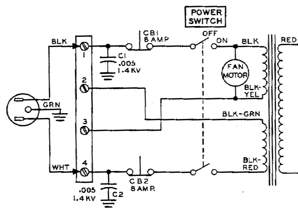
SB-200 power supply input stage
The original design works by taking line voltage and running it through transformer T1 to bump it up to ~800V RMS, or about ~1150V PtP. Nowadays with modern household voltages up around 120v in North America, this is closer to 1230V. From here on out I’m calling it 1200v. There are two equal primary coils on the transformer, able to be wired in series or parallel for either 110v or 220v operation. Each input leg of the transformer is protected by its own circuit breaker. This is necessary because the switching for series or parallel operation of the input primaries is done before the circuit breaker, which means if they are operated in parallel for 110v input then if the circuit breaker went off on one the other would still be energized without its own breaker. It could have been wired with the circuit breaker before the split and they could have gotten away with one, but I like this design the way it is. It works well for people in North America who choose to operate it on 220V. In North America, each leg (black and red) of a 220v line is hot with respect to neutral (white) and ground (green). This means a single pole circuit breaker on a 220v line can trip and you still have live power through the other leg with respect to ground. The two-breaker design ensures that whether you wire it for 110v or 220v either in North America or internationally, you are equally well protected.
Power Output:
T1 has three secondaries, one 800v for the main high voltage power, which we are interested in here, and two others, 6.3v and 110v for the heater/lamps and tube bias which I’ll cover later. The 800v output goes to a modified Delon circuit for voltage doubling. This is what we see on the high voltage board, and this is the board that is commonly replaced with a Harbach one.

SB-200 power supply high-voltage circuit
The voltage doubler works by charging two banks of three capacitors each to the maximum peak-to-peak voltage. When the transformer output line labelled “RED” is positive, it charges C4 – C6. When it’s negative, and RED-YEL is positive, then it charges C7 – C9. Eight diodes and three capacitors are used in series in each bank so as to handle the full peak-to-peak voltage voltage. A resistor (R5 – R10) is wired in parallel with each capacitor for two reasons, to act as a bleeder when power is off and as a balancing resistor for series charging. More on the balancing resistors below. Rounding out the circuit are resistors R11, R12, and R13. R11 forms a voltage divider with R10 to tap 10V off of the last capacitor’s 400V. This voltage is used for the Automatic Level Control feedback from the amplifier back to the exciter. R12 is similar – it forms a voltage divider between the entire capacitor network and ground and is used to measure the plate current without measuring bleeder current. More on this in metering.
Balance Resistors
As mentioned, the capacitors are charged in two series banks of three capacitors each to handle the 1200v per bank. When you are charging capacitors in series, you need to account for the leakage current through them. Every capacitor leaks a little current, and electrolytic capacitors more than others. If the leakage currents were identical, then you wouldn’t need to worry. But that’s not the case. Each capacitor (even ones produced in the same batch) can have a different leakage current, which means when they are wired in series and you are forcing the same current through all three, they will all rise to different voltages. Let’s imagine that two have high leakage currents and one has a low leakage. Higher current means less “effective” resistance, and lower resistance means a lower voltage drop. But that 1200v total has to go somewhere, so if two capacitors are taking proportionally lower, then the one with the low leakage current will be taking proportionally more and may exceed its maximum voltage. So the balancing resistors essentially put an intentional leakage past each of them that is relatively high compared to the actual leakage. This balances out the voltages.
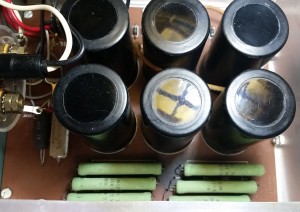
SB-200 – Original high-voltage board
Back in 1964 capacitors had larger leakage currents which required even more current through their balancing resistors. R5 – R10 are each 30KΩ resistors, and they are rated at 7w because at 400V per capacitor, a 30KΩ balancing resistor burns through 5⅓W. Now I have no problem with Heathkit’s logic here, it was necessary after all. What I have a problem with is where they put them. Take a look at the photo of my board. At 5⅓W per resistor, that’s 32W of heat being produced right beside those capacitors. My capacitors are, luckily, all in really good shape – I don’t think my unit was used much,What I couldn’t really show, due to the angle, was that each capacitor is about 7cm (2¾”) tall. And they are black. Which all means the resistors are radiating heat on the bottom of the board and that the capacitors are just soaking up because there is no ventilation on this side of the unit.
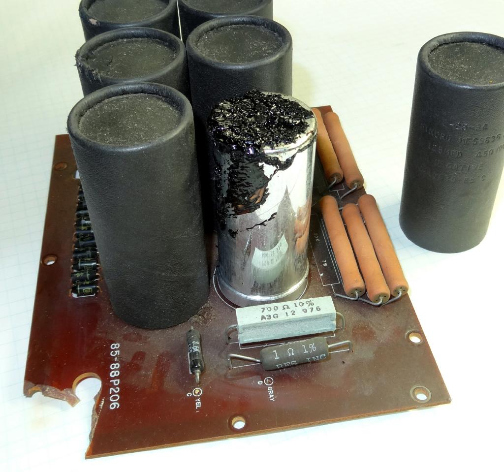
Leaked electrolyte in a bad SB-200 board, courtesy of Doug Crompton (WA3DSB)
These little space heaters are the reason for most of the capacitor failures in these units. One of two things should have been done here. A better design would have been to mount the board higher, hang the capacitors off the bottom and having the resistors on top. This would keep the board between the resistors and capacitors and have the heat free to rise up away. Even a little heat-shield divider placed between the resistors and capacitors to protect them from the heat would have been better than nothing. Something to separate that heat from the capacitors. The capacitors on my unit seem to be in good condition – excellent actually, but you can see here on the board of a unit that is a little older than mine what effect those lovely heaters have had.
Common Power Mods
There are two very common mods people purchase for the SB-200’s power supply system, both of them from Harbach.
Harbach PM-200 Power Board

Assembled Harbach PM-200 board, courtesy of Doug Crompton (WA3DSB)
One of these is their PM-200 replacement high-voltage board, shown at right. As I understood it, one of the original purposes of this board was to give you something with modern capacitors having much lower leakage currents so that the balance resistors could be increased in value and reduce the quiescent power draw of the unit. That’s what most SB-200 project pages state. And on Harbach’s page for the module they tell you they are using “new 82KΩ 3W bleeder resistors” – but what they don’t tell you is that they are using two of them in parallel for each capacitor. That’s 41kΩ, burning 3.9 watts per capacitor for 23.4 watts total – and again, all of the resistors are placed right beside one bank of the capacitors. So the Harbach board is no real benefit at all. They are either using cheap capacitors with very high leakage currents, or more likely are basing their balance resistor values on outdated thinking (see below). Harbach’s capacitors are physically smaller than the originals, and the resistors are burning slightly less power, both of which mean the capacitors won’t get quite as hot as on the original board. But unless your original board is physically cracked, I see nothing about the Harbach PM-200 board that is tempting.
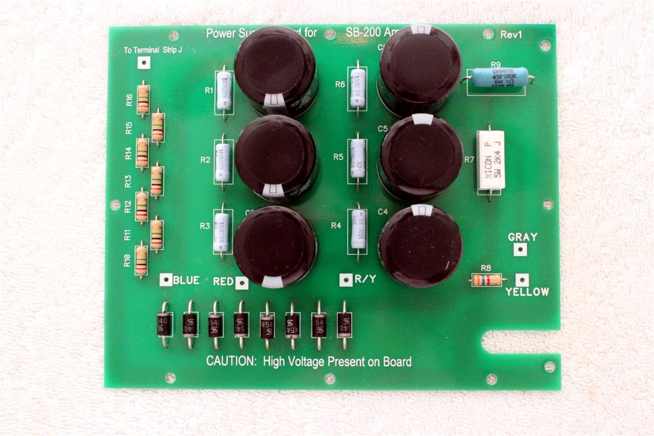
K4LAJ’s SB-200 HV power board – note the balance resistor values and placement
If you are in the market for a brand new board, then a better solution might be the one created by fellow ham Don Van Wagner (K4LAJ). He operates a small-volume business under the eBay seller name vanwagnd112. He sells fully populated and assembled power boards. Note that he’s using 100KΩ balancing resistors (burning 1.6 watts each for a total of 9.6 watts) and that he’s designed it so each resistor is located beside the capacitor it balances. There is less waste heat, and that heat is more evenly distributed. I will note, though, that while I can say that the 100KΩ is more in line with the leakage current in modern capacitors (and even less than I’ll be using – see below), without seeing the data sheet for these capacitors I can’t say for that this is an appropriate value in this case. It’s certainly a much better layout.
Harbach SS-201 Soft Start
The Harbach SS-201 Soft Start board is the other common (almost ubiquitous) mod that SB-200 owners are installing. My feelings on this board have changed over the last year. In draft versions of this article I wrote that the board was unsafe. And while I still don’t think the circuit is the best design, I’m not prepared any more to actively call it unsafe. I will say I believe it unnecessary.
The Harbach soft start board works by running two 10Ω 10W (for 110V operation) resistors in series with the incoming AC mains power for what Harbach says is “a fre milliseconds” when the device is powered up, then switches them out and runs AC mains power directly in. The intention is to limit the inrush of power in the amp (ie: filaments) and power it up gracefully. Two relays do the switching. When the relays are in their normally closed configuration, the resistors are switched in. When the relays are powered, then the resistors are switched out. That makes me uncomfortable because the most common failure mode for any relay is for it to fail closed. Which means if one of those relays fails, then the resistor will be left in series with mains power switched in. If a relay does fail, what happens?
- One or both relays fail.
- 110V power is now directed through the soft-start 10W resistors
- The amp is not being keyed, so the power supply is drawing between 10-30 watts depending on the power supply board installed. Worst case, 30 watts. A 10 watt wire wound resistor won’t let go with 30 watts going through it (at least not for a long time), but it will get very hot. What effect that has depends on where in the case the board is mounted. It likely won’t get hot enough to start a fire at 30 watts, but it could easily melt through wiring. This could be catastrophic right there, but lets say not. Other than potentially melting wiring, unless your front meter is switched into the HV line, there won’t be any real indication that the relay has failed. The lights will come on. The fan will come on. But then at some point…
- The operator will key the exciter’s mike. Or, more likely, key the CW to tune up the amp. At this point, I work out that the there will be about 380 watts of power dissipating through those 10 watt resistors. The outcome is a foregone conclusion.
I’ve only seen 10W resistors let go a couple times, and both times it was like a small pyrotechnic. They are not designed to be fuses, letting go gracefully when too much power flows through them. They are designed to be tough and try to dissipate just as much heat as they possibly can. They have a strong ceramic housing, which in this case just acts as a pressure vessel. By the end of the scenario, they will already have been very hot, and possibly have already melted wiring and plastic housing on the nearby relays, so when they let go they can spread hot melted plastic and ceramic and wire bits all over. And, by design, this board is mounted very close to the HV power board and close by the input terminals where AC mains power is coming into the machine.
How likely is it that one of those relays will fail? Admittedly not bloody likely, which is why I’ve backed off saying these boards are unsafe. Most relays are rated for millions of cycles. I just find it ironic that most people who own these amps will install a couple of protection diodes across the meter just in the off chance that something does fail (because the meter is irreplaceable), but they then seem to be blissfully happy to install a soft start board where they are adding a point of failure there is no protection for. The way I see it, anyone with this board in their amp is one Chinese-manufactured relay failure away from a fire in their amplifier.
That is an unlikely scenario. So let’s analyze what goes on during a typical “soft” start. What does a soft start board buy you anyway? Its intended purpose is to reduce inrush current “for a few milliseconds” at startup, thus reducing strain on your tube filaments and on the HV board’s rectifier diodes. I have read about a lot of SB-200’s with failed components, I have yet to see a report for one where the rectifier diodes let go. They have a lot of surge capacity. And for the tubes, filament failure is by far one of the least common failure modes for a 572b. Now why is that? After all, studies have shown that soft start modules in general do help prevent vacuum tube filament failures, so why do the 572b filaments (and power amplifier tube filaments in general) so seldomly fail? Filament inrush current, while theoretically very large, is in practice limited by the transformer. In an SB-200 (and almost every other similar amp) the filament inrush is competing against the large voltage doubler power capacitors for that initial surge current. A cold 572b filament measures at about 0.3Ω, which means it wants to draw 21A surge current at startup. That drops to less than twice the nominal current of 4A after ten milliseconds and the current inrush period is essentially ended. It is guaranteed that for that for at last the first 16.7 milliseconds (the time of one power cycle) your HV power board capacitors will have far less effective resistance than the tube filaments and will essentially be drawing all the current the transformer can produce. Which means for far longer than the “few milliseconds” that a Harbach soft start board is active at startup, your HV board power capacitors in concert with your transformer are acting to limit how much current your tube filaments are getting anyway. In fact, the filament surge period isn’t even over by the time a Harbach board switches its current limiting resistors out of the circuit.
So my conclusion for any tube amplifier with large capacitors in the power board, the Harbach soft start board is completely unnecessary, and essentially ineffective. Mommy medicine that will make you feel better for putting it in, but does nothing for your amp.
Refurbishment Plan
HV Board
My HV power board is in excellent shape. When operating, there is between 400-410 volts measured across each capacitor. That is a very small spread and it tells me the capacitors are in good shape relative to each other. I hate the idea of pulling out and replacing perfectly good, and original, components from a working piece of gear. However, as noted earlier, this is a critical board and I’m just not comfortable with leaving resistor-cooked capacitors that are no less than 30 years old sitting in it. This amp isn’t going to sit idle – it’s going to be used, and well used. I’m not going to jeopardize everything else in the unit.
Before I found Don Van Wagner’s excellently designed board, my plan had been to simply replace the capacitors and required resistors in situ on the original board. After finding it, though, I came up with a new plan. Having a fully stock SB-200 in working order is becoming rarer, so rather than pull good components off the old board as a just in case, I’m going to replace the board outright and keep the old one fully intact. That gives me the option of returning the amp to its stock configuration some time in the future.

New capacitor placement on old board, shown from underneath
The old plan would have worked fine, so if you have a board that already has bad component, then by all means refurbish it. I don’t think I would have had to do anything drastic to the original board to make new snap-in capacitors work, as shown in the diagram. I would have needed only jumper the negative lead. You will still end up with the resistors all on one side, but there is a great solution for the heat issue. Technology to the rescue.
Balance Resistor Redux
This section ended up being very long. When doing research on balance resistors I encountered a lot of rules of thumb and old thinking and had to dig. I spawned off the explanation into a paper on balance resistors for series capacitors. Condensing this down, the formula I recommend for balance resistors is:
R_{balance} = \frac{NV_{rate}-V_{bus}}{I_{\Delta bleed}}
Where:
- N is the number of capacitors in series
- V_{rated} is the rated maximum voltage for any one capacitor
- V_{bus} is the bus voltage – the expected voltage across the whole series of capacitors
- I_{\Delta bleed} Bleed current difference in µA
You end up with R_{balance} in megohms
This formula calculates the total voltage “headroom” you have in the series bank of capacitors series and divides it by an estimation of the difference in bleed current. I used Cornell Dubilier’s formula for estimating this:
I_{\Delta bleed} = 0.0015CV_{bus}
I ordered six 390/muF 500V Nippon Chemicon “LXS” series capacitors from Ali Express. I got the 500V rated capacitors since they are common enough now so as not to be expensive, and they give a lot of voltage headroom. A voltage doubler works by charging two banks of capacitors independently and then adding them together for discharge. They are being charged in two banks of three, so this works in the above formulae as:
R_{balance} = \frac{3 \cdot 500V - 1250V}{.0015 \cdot 390{\mu}F \cdot 1250V} = 0.341M\Omega
Even adding in a safety factor of two (and then rounding to give a power burn of an even one watt), the 160KΩ value I chose is less than what the old rules of thumb state.
The rest is UNDER CONSTRUCTION