
Introduction
I was recently conducting research for refurbishing my old Heathkit SB-200 Linear Amplifier. The power supply board in it uses a voltage doubler to achieve 2400V DC output – a pretty hefty punch. Several aluminum electrolytic capacitors are used in series because the voltages involved exceeded what any commonly available single capacitor could handle. Working with capacitors wired in series, as I came to learn, isn’t as simple as just wiring them up that way. You have to account for different properties of the capacitor that can cause the voltage of one or more of them in the series bank to wander, potentially exceeding its rating. Balancing resistors (sometimes inappropriately called bleeder resistors) are required to ensure the voltage load is spread evenly among all capacitors in the bank. This article speaks to what the reasons are for this, what all is involved in making sure your capacitors are properly balanced, and how to make sure you’re not wasting too much power (and generating too much heat) doing it.
There isn’t a lot written about this topic. Unfortunately, what is written often cites old rules of thumb that are either no longer relevant or wildly inefficient. And some of what is written, even by capacitor manufacturers, is misleading or just patently wrong. So after we look at the issues involved, we’ll dispel some myths and hopefully clear some cobwebs out of the collective consciousness on this topic.
References
The following references have been invaluable research aids. Some for the excellent information they contain, some as examples of how to tell someone just enough to be dangerous.
- Application Guidelines for Aluminum Electrolytic Capacitors, Nichicon Corporation, retrieved 9 Sep 2015
- Aluminum Electrolytic Capacitor Application Guide, Cornell Dubilier, retrieved 9 Sep 2015
- Engineering Solutions: Aluminum Capacitors in Power Supplies, Vishay Intertechnology, retrieved 9 Sep 2015
- Strategies to Repair or Replace Old Electrolytic Capacitors, Tim Reese, Retrieved 10 Sep 2015
- Voltage Balancing Resistors, Illinois Capacitor, Retrieved 10 Sep 2015
The Issues
In an ideal world, every component with the same ratings would be identical. Unfortunately in the real world we have to deal with imperfect components, and when it comes to aluminum electrolytic capacitors we are talking about some of the imperfectest of the bunch. They have some of the widest tolerances of any component, plus they go out of spec after disuse. Sometimes it will seem like you are shooting at a moving target, as this is a type of component that can actually change value on you in situ.
The areas we have to account for fall into three major areas of consideration:
- Capacitance Tolerance
- Leakage Current
- Dynamic Effects
Capacitance Tolerance
Most passive components have tolerances – the amount by which the component can be off of what it’s rated value is. Over the years, of course, manufacturing techniques have improved these tolerances. A tolerance of ±20% was once the norm for resistors, and now you can easily buy them with a tolerance of ±1% and the price difference from is so low it doesn’t matter. However the tolerance for large aluminum electrolytic capacitors, even nowadays, is still generally ±20%.
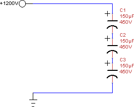
1200V Circuit with Three Capacitors in Series
That’s the bad news because it means that for any two capacitors of the same rated value, if one is on the high end and the other on the low, they can be different from each other by as much as 40%. Consider the simple circuit to the right, where the capacitors have to, together, handle 1200V. It seems reasonable to expect we could use three 450V capacitors in series. Given that they could be as much as 40% off of each other in value, though, it’s a good idea to check to see what the maximum voltage would be that we could see on a single capacitor. We know that the voltage across a single capacitor in a series circuit is proportional to how much capacitance it has relative to the capacitance of them all added together. So the worst case is if one capacitor is up by 20% (180μF) and the other two are down 20% (120μF each). V_{Cn} = V_{total} \cdot \frac{C_n}{C_1 + C_2 + C_3} so if we assume worst case: 1200 \cdot \frac{180}{180 + 120 + 120} = 514V
That was the bad news. The good news is twofold. First, the worst case is very very unlikely and secondly, it’s very preventable. In many cases foreknowledge is power, and that certainly applies here, so a capacitance meter is your friend. Capacitors built in the same batch tend to have very similar values. So to mitigate voltage differences caused by differences in capacitance, buy your capacitors together in groups so as to maximize your chance of getting ones made in the same batch. My experience purchasing them in groups (from wide variety of manufacturers) is that they all tend to fall within a couple percent of each other.
Leakage Current
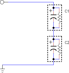
All capacitors can be thought of as having a small resistor in parallel
The other issue tending to alter the voltage across a capacitor in series is its leakage current. All capacitors leak to some extent, and the aluminum electrolytic capacitors you find in power supplies are the worst offenders. You can think of anyactual capacitor as if it’s an ideal capacitor with no leakage in parallel with a resistor. Together, as a package, they make up a real-world capacitor.
Why Leakage Current Is a Problem
If the leakage currents in all your capacitors were the same, there would be no issue here. The problem being that this is not necessarily the case. The leakage for two capacitors, even of the same value, can be different. And if you place capacitors with different leakage currents in series with each other, you are forcing the same current through all of them. So, just like putting different resistors in series with each other where you force the same current through each, the voltage across each one changes. The same thing happens in the capacitors. The lower the leakage current is in one capacitor (compared to its partners), the higher the voltage will be. Lower current means higher “effective” resistance, and higher resistance means a higher voltage drop. This is actually the problem in this scenario. As capacitors age, or as they heat up, their leakage currents increase. That means that the capacitor that is having leakage problems isn’t the one that the voltage is going to rise on. Now this can cause a certain amount of self-correcting. As the voltage rises on the bad capacitor’s neighbour will see increased voltage and it will start to “wear” more heavily and start passing higher leakage currents itself, which can balance things out. This is the most likely scenario, but not the only one and there are many failure modes on an electrolytic capacitor (especially in an over-voltage situation) that include shorting. Simply put, if you have the kind of circuit where you need to use multiple capacitors because of the high voltage, then letting the voltage rise too much in any one capacitor is not something you want to do.
Typical Leakage Current Calculations
The maximum leakage current you can expect from a capacitor is given in its data sheet, usually in a short formula you punch the capacitance and voltage into. Typical formulae I’ve seen on recent data sheets for large aluminum electrolytics:
- Samyoung: I_{leak} = .02CV
- Jiangha: I_{leak} = .01CV
- Nippon Chemi-Con, Nichicon, CDE: I_{leak} = 3\sqrt{CV}
All the above report leakage current in microamps. Samyoung’s leakage stats are the worst I’ve seen for recently manufactured capacitors. Jiangha’s formula suggests their leakage is lower for smaller capacitors and/or lower voltages, whereas Nippon Chemi-Con’s (et al) formula reports better stats with increasing voltage and capacitance with the break even point being 200µF at 450V.
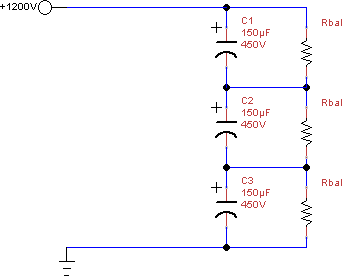
Same 1200V circuit with balance resistors added
Now there really wasn’t much you could do (or, as you’ll see in the myths section later, need to do) about voltage differences due to capacitor tolerance besides ensuring your capacitors were close to each other in value before you use them. This isn’t the case with leakage current. So now that we have our leakage current figured out for the capacitor we want to use – what do we do with it? This is where the balance resistors come in, and this is where the fun of figuring out what size to use starts.
Balance Resistor Rules of Thumb
Where do we start? When researching this, the most common (old-school) rule of thumb I saw for choosing the resistor value was to make it pass a certain multiple of capacitor’s rated maximum leakage current. Most forum posts suggested three times the capacitor’s maximum bleed current. This, as it turns out, can produce a number that’s reasonable though you’ll likely end up wasting power. Some, typically older, posts and even one very misguided manufacturer’s(Illinois Capacitor’s) application noteRefE advocated ten times the rated leakage current! This is intended to “swamp” the leakage current – run so much bypass current around the capacitor that the relatively small amount of leakage current through it is negligible. Now if you’re in a situation where you can’t afford even a small voltage rise on any capacitors, then maybe…maybe…running a balance resistor with ten times the leakage current might be necessary, but even if this is the case there are better ways to determine what exactly you need. And at the voltages we’re looking at, which is around 400V per capacitor, at ten times the leakage current you’ll end up with a resistor burning through 5 – 10 watts of power. Leakage current rises very rapidly with temperature, so putting what amounts to a ten watt space heater in close proximity to a capacitor in an attempt to control leakage current effects is extremely counterproductive and can lead to thermal leakage current runaway. But that aside, the major problem with these methods is that they are blindly trying to address the issue. They don’t really take into account leakage current differences between capacitors. Remember, we’re not really concerned about how much leakage current there is. We’re concerned with how different the leakage current between two capacitors is. And these methods, they assume that if the maximum leakage current is X, then the maximum leakage current difference between the capacitors is also X. And that just isn’t necessarily, or even often, the case. These methods also don’t take into account how much voltage rise your components can accept; they leave you running blind without any sense of what voltages you might actually see given any particular choice of balance resistor.
A Better Way
There is a much better way to approach the balance resistor problem. And all it takes is some simple math. A more modern calculation for the balance resistor that takes into consideration what the difference is between what your capacitors are rated and what total voltage you need them to handle is:
R_{balance} = \frac{NV_{rate}-V_{bus}}{I_{\Delta leak}}
Where:
- N is the number of capacitors in series
- V_{rate} is the rated maximum voltage for any one capacitor
- V_{bus} is the bus voltage – the expected voltage across the whole series of capacitors
- I_{\Delta leak} Leakage current difference in µA
You end up with R_{balance} in megohms
Basically this formula calculates the total voltage “headroom” you have in the series bank of capacitors and divides it by an estimation of the difference in bleed current. This is far better than the “shoot from the hip” rules of thumb of X times the max bleed current.
All that remains is working out the maximum difference in leakage currents. For 100% safety, you can still use decide that I_{\Delta leak} = I_{maxleak}. However, if you have purchased your capacitors from the same manufacturing batch in order to minimize tolerance differences, it is almost certain that they share similar leakage currents.
Cornell Dubilier Electronics suggestsRefB an interesting formula to determine the difference in leakage currents in a multi-capacitor environment:
I_{\Delta leak} (in {\mu}A) = 0.0015 \cdot C \cdot V_{bus}
It’s not entirely clear how they derive this – specifically where 0.0015 comes from is unknown. Either a simplification, something determined experimentally, or a combination of both. The formula is similar in form to some of the ones published to determine maximum leakage currents, with a lower constant by a factor of six. This suggests they are confident that the leakage currents in their capacitors are generally pretty close to each other. CDE is the only company I’ve seen to formally publish a method of determining I_{\Delta leak} independent of I_{maxleak}. Their formula produces values which seem to be in line with what I’ve seen for actual leakage current differences in capacitors from most of the manufacturers I’ve purchased from recently. It should also be noted that CDE’s maximum leakage current formula is the same as the one used by both Nichicon and Nippon Chemi-con. While this doesn’t necessarily imply that their manufacturing methods also produce capacitors with similar leakage currents to each other, it’s likely to be in the same ballpark for those manufacturers.
Thus, if you combine the better method of determining balancing resistor values with CDE’s formula for determining I_{\Delta leak}, you get the following:
R_{balance} (in M\Omega) = \frac{NV_{rate}-V_{bus}}{0.0015CV_{bus}}
Our 1200V, Three Capacitor Circuit
So, if we go back to our example three capacitor bank, each 150 \muF capacitor is rated at 450V, and V_{bus} is 1200V:
R_{balance} = \frac{3 \cdot 450V - 1200V}{.0015 \cdot 150{\mu}F \cdot 1200V} = 0.55\overline{5}M\Omega
I could have picked better numbers for an example, but then again, real life numbers rarely work out well and the above is close enough to a standard 560k resistor that the difference wouldn’t matter. What we can take away from this, is that if our assumption that I_{\Delta leak} = 0.0015CV_{bus} and that it accurately represents the greatest current difference that we will see between the capacitor with the highest leakage and the one with the lowest, then the voltage on any one capacitor will never exceed its rated 450V.
I would, of course, encourage adding in a safety factor. The above 560K\Omega resistor at the nominal 400V per capacitor voltage will only burn 285mW of power, which is exceedingly low compared to what most balancing resistors in similar circuits burn. You could easily half the resistance, give yourself a times two safety factor, and still only be burning a little over half a watt per resistor, which leads us into the next factor to consider when choosing balancing resistors:
Dynamic Effects
As alluded to earlier, sometimes working with aluminum electrolytic capacitors is like shooting at a moving target. Several factors work to change the properties of these components. These capacitors are composed of ultra-thin aluminum foil that is etched to increase its surface area then rolled with an electrolyte between the layers. When I first learned about electronics in high school, I naively thought it was the electrolyte that was providing the dielectric. This isn’t the case – the electrolyte simply helps aluminum oxide to form, and that is what provides the dielectric.
Periods of disuse will reduce the the thickness of this aluminum oxide layer. Less dielectric means lower capacitance (which will likely drive up ripple in your circuit). It also means that, since the aluminum oxide is an insulator between the aluminum layers, that a thinner layer of it causes more leakage current. Sometimes, significantly more. This isn’t wholly bad, since it is this leakage current which powers the electrolytic process that reforms the dielectric layer. As the disused capacitor is used used again, the electrolyte self-heals the aluminum oxide layer and the capacitor returns to normal operating parameters. Analyzing aluminum electrolytic capacitors, how they age, and how to reform them is almost a whole field of study in and of itself. There are many good articles on this, such as the one at reference D. The takeaway from this is that leakage currents go up with disuse, and that leakage current differences between your capacitors can tend to multiply when this happens. This is something to consider, and one reason why, if you do use the formula above, that it encouraged to adopt a safety factor of around two. Additional safety factor can be obtained by using higher voltage capacitors. In the SB-200 refurbishment that sparked this article, the balance resistors were calculated assuming 450V capacitors, although 500V ones were actually employed. It is quite common to see 500V or even higher voltage capacitors now, and this can be a source of safety margin. The choice to use 500v capacitors rather than 450v gave a safety factor of two immediately (since the nominal voltage was 400V per capacitor, calculating for 450V and using 500V doubled the voltage headroom), which was further increased by lowering the balance resistors in value about 35% so as to draw an even one watt each.
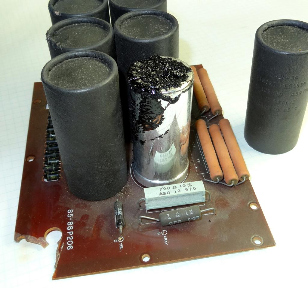
Leaked electrolyte in a bad SB-200 board, courtesy of Doug Crompton (WA3DSB)
The other dynamic effect you need to account for is heat. Heat is a capacitor killer. As you can see from the SB-200 power supply board to the left, all the balance resistors were placed on one side, essentially cooking the right hand row of capacitors. This runs the risk of thermal runaway, since leakage current can rise sharply with temperature, which then heats the capacitor further. Ripple is another big cause of capacitor heat, though it’s beyond this article’s scope to discuss in depth, remember that as a capacitor heats its capacitance reduces, which likely increases your ripple. All these things make it a very good idea to keep your capacitors cool. Reducing the size of nearby balancing resistors (when safe to do so) is one way to accomplish this. Staggering the locations of balancing resistors so they aren’t all bunched up together is another way. You can also consider mounting the capacitors and their balancing resistors on opposite sides of the circuit board to use the board to reduce thermal flow, though you have to be careful the board doesn’t trap the heat in – creative mounting solutions can help here. You can also consider providing fan cooling for them.
Balance Resistor Myths
Now that we’ve covered the three major issues that affect choice of balance resistors, let’s look at some of the myths surrounding them – some we’ve already looked at, some are new.
Myth #1: Tolerance AND leakage both have to be considered together
Some sources suggest that when you are calculating your balance resistor, that you need to account for the voltage differences caused by differences in capacitance AND voltage differences caused by differences in leakage currents together. The normal method employed is to calculate the maximum voltage you might see assuming two capacitors are as far apart in capacitance as their tolerances allow, and then take the highest voltage and use that as the circuit’s nominal per-capacitor voltage when calculating the value of the balance resistor using the formula given above. This is for the most part false. The reason this is false is that voltage differences caused by different values in capacitance and voltage differences that occur due to different leakage currents occur at different points in the charging cycle.
When you first start charging a capacitor, the charging current is (for any purpose where you will be stacking capacitors in series anyway) so much larger than the leakage current that the leakage current is entirely irrelevant. It is during the charging cycle that differences in capacitance between the capacitors in a series bank will cause the voltage across each capacitor to be different. It’s only when a capacitor is very nearly fully charged that leakage current differences become a significant factor in determining the voltage across each capacitor, and at this point, differences in capacitance are essentially irrelevant.
So, to sum up, in a series bank, voltage differences due to differences in capacitance occur during charging, voltage differences caused by differences in leakage current occur when the bank is charged, and there is a fairly smooth handoff from one to the other that makes accounting for both together unnecessary.
Myth #2: Three times the leakage current is a good rule of thumb for determining balance resistor values, or
Myth #3: Ten times the leakage current is the safest way to determine the balance resistor value
These rules of thumb leave you blind to what is actually occurring in your circuit and can in certain circumstances be unsafe. They do not account for the voltage headroom between your capacitors rated voltage and the circuit voltage. If there is little enough headroom, even “swamping” your leakage current by having your balance resister draw ten times that much can cause the voltage to rise over rating. If you are looking for absolute safety, it is far far safer to use the headroom formula above and, instead of using CDE’s formula for determining the leakage current difference, assume that the leakage current difference is equal to your maximum leakage current:
R_{balance} = \frac{NV_{rate}-V_{bus}}{I_{maxleak}}
This will always be the safest bet, better than any of the earlier rules of thumb. I say “safest”, by that I mean the voltage across any one capacitor will never rise above its rated voltage that way, but then you are likely burning a lot of heat in your balance resistor and you need to be careful not to be cooking your capacitor.
Conclusion
Many factors affect a capacitor’s leakage current, its longevity, and its health. All of these factors are important to consider when choosing the value of and placement for your series capacitor balancing resistors. You may think you’re being extra safe with that large, high wattage resistor and then end up placing 60 watts of resistors right beside one bank of capacitors and cooking them to death.
Further, simplistic rules of thumb for determining your balance resistor values leave you in the dark, and tend to produce resistors that burn more power than is required for modern capacitors. Using the formulae given above you can make your own tradeoff between power wasted and capacitor voltage rise with eyes open, not blindly hoping that some years gone rule of thumb will keep your high voltage power supply safe.